electrical
Electrical: roamr’s electrical components are consolidated into a power PCB and a motor PCB. Below is a breakdown of our entire electrical system.
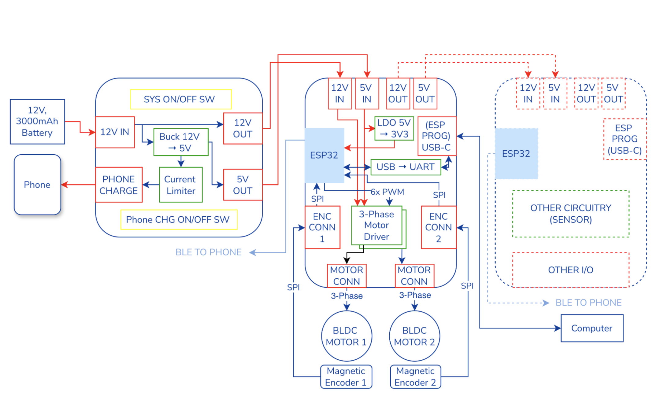
We decided to go with a modular and “nodal” electrical architecture. There is one overarching power PCB that interfaces between the battery and the remaining modules. Each module both inputs 12V and 5V, and outputs 12V and 5V for a daisy-chaining power topology. Each module should have its own ESP32 that supports BLE, which will all individually connect to the iPhone. We decided to go with this design since an iPhone can concurrently connect with many BLE devices in parallel. We saw this as an opportunity to decentralize the hardware from a single “brain” that controlled the whole robot, and instead have each model as its own BLE node. This modular system enables scalable hardware extensibility, where modules can be easily added and removed as needed, without need for an entire electrical redesign.
For this edition of the robot, we have one module, which is the BLDC driver board. See below for a picture of each PCB and a breakdown of its functions.
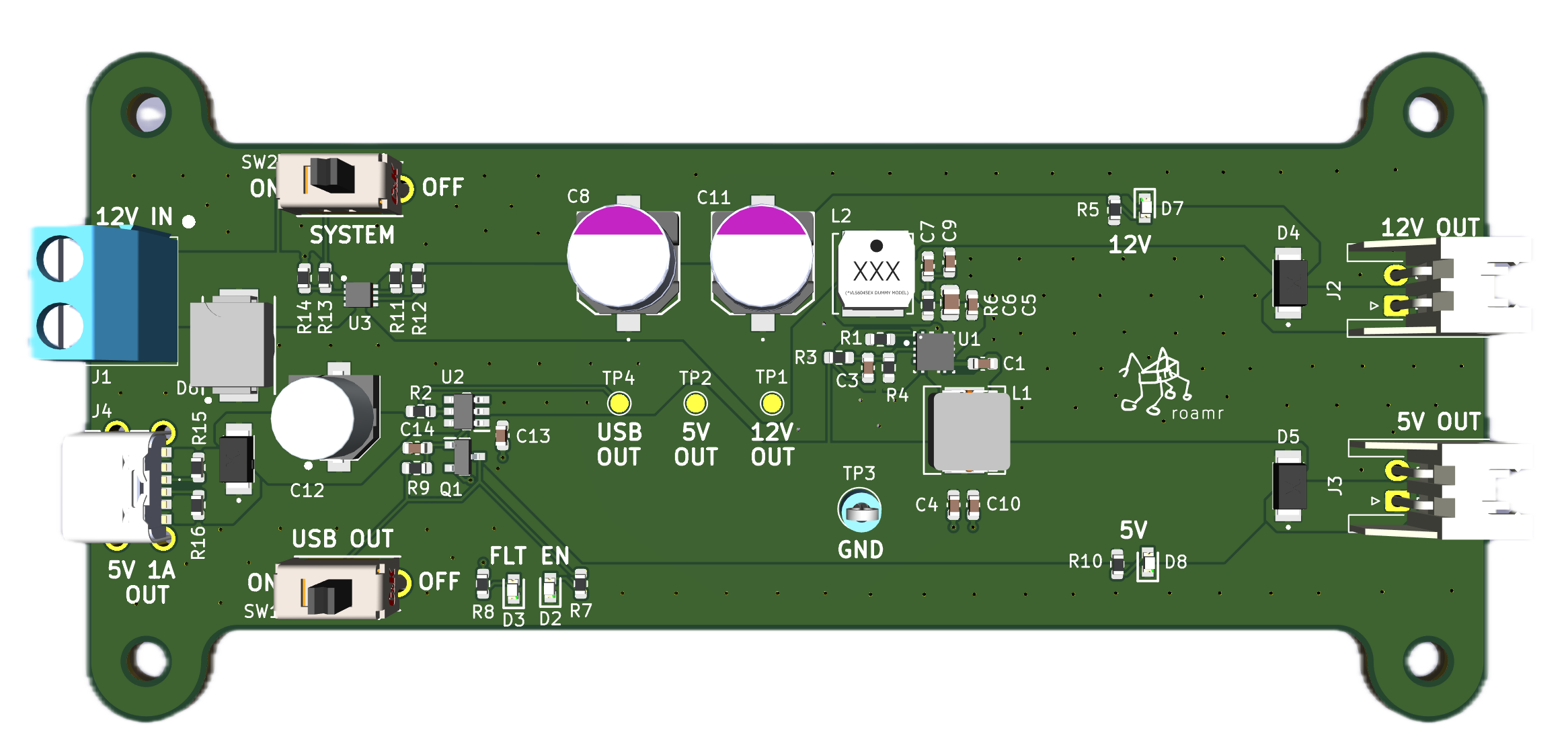
The power PCB takes in 12V from a battery, and provides three main functions: 12V pass through, 12V to 5V stepdown, and 500mA (USB Default) phone charging through a USB-C port. There also features two switches: a switch to cut the input power from the main system, and a switch to toggle on-off USB-C charging. We wanted to reduce the amount of plug/unplugs needed from the robot, so we opted to include these switches for ease of use.
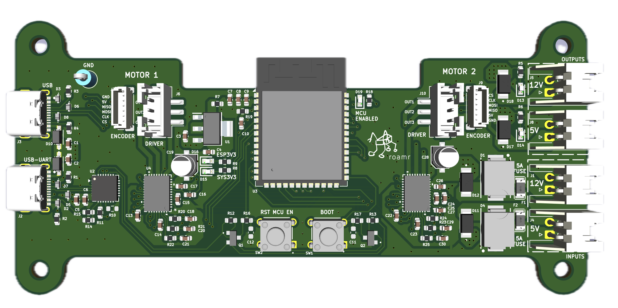
The motor PCB takes in 12V and 5V from the power PCB. The 12V is used for the three-phase motor drivers, while the 5V is fed to the encoders, and also further stepped down to 3.3V through an LDO to power the ESP32 and the off-board encoders. Throughout the board, SPI is used for ESP32 <-> motor driver communication, as well as ESP32 <-> magnetic encoder communication. A USB-C port is provided to communicate (flash, monitor) with the ESP32 through a computer, with a USB <-> UART bridge enabling communication between the two.
For the motors, field-oriented-control (FOC) was used as the control method.